Due: 5:00pm, Thursday, October 10. Value: 30 pts.
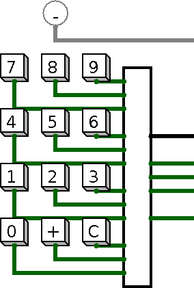
The summer.circ file implements a simple keypad in Logisim, shown at right. [Link] (You may need to right-click the link and select “Save Link As…” or “Save Target As…”.) You can see six wires sticking out the circuit's right side.
Your job is to fill out the circuit so that it works like a 16-bit calculator that only does addition. For example, the following sequence shows how the display should update with different keys being pressed.
Button Display 4 4 5 45 6 456 + 456 3 3 + 459 5 5 4 54 1 541
Button Display (continued) + 1000 C 0 3 3 C 0 8 8 + 8 9 9 + 17
You may add any of the following components to your circuit:
Wiring library: any component Gates library: any component Plexers library: multiplexer and demultiplexer only Arithmetic library: adder only Memory library: D flip-flop and register only Input/Output library: no component Base library: no component
You'll need to be familiar with Logisim's “wire bundles” for this assignment; you can read about them in the “Wire bundles” section of its documentation.
In building your circuit, I suggest including two 16-bit registers: one to hold the current number being entered, and another to hold the sum of the previous numbers entered. I also suggest using a single D flip-flop that tracks whether the last button pressed was “+” (in which case the sum of previous numbers should be displayed) or a digit (in which case the current number should be displayed). For the clock input on the registers and flip-flop, you would want to use the keypad's bottom output. The registers would each employ a multiplexer to control how the register should update with the keypress.
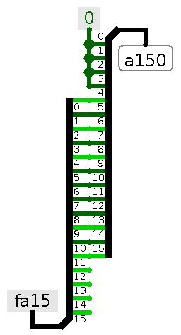
With each press of a digit button, you'll want the current number to update to 10 ⋅ current + digit (akin to the square.c portion of Assignment 2). To compute 10 ⋅ current, you'll want to use left-shift and addition circuits. This brings up the question of how to perform a left-shift in Logisim. The circuit at right illustrates a four-bit shift using two 16-bit splitters and a constant-0 component; given the input of 0xFA15, it yields 0xA150.
I suggest that you start your circuit by first making it so that pressing multiple digit keys properly accumulates a number into a register (i.e., ignoring the “+” and “C” keys). Then you would enhance it to support “+” and “C”.
On the Linux computers, you can execute Logisim by entering the command “logisim &” at the terminal prompt. You can also download Logisim freely as directed on its Web page. It runs on Linux, Mac OS X, and Windows.